
The CERN Trajectory Measurement System
 This project was carried out with Alpha Data Ltd and involved the design, construction, commissioning, support and maintenance of a new trajectory measurement system for the CERN Proton Synchrotron.
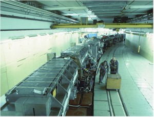
The TMS system was designed to measure the trajectory of particle beam's within the CERN Proton Synchrotron. It is able to measure the amplitude, x/y displacement and timing of the individual particle bunches as they pass each of the 40 analogue sensors in the ring. The system integrates the data received for each particle bunch and stores the results in memory for later data access. In order to accurately measure the particle bunches the system uses, FPGA implemented, digital phase locked loops to synchronise the data capture to the incoming data.
The system continuously samples 120 Analogue channels at 125MHz, 14 bits and processes this data in real-time to determine information on the position of particle bunches as they orbit at around 437kHz. The system captures and processes around 15 billion samples per second. Multiple Xilinx Vertex 4 FPGA's are employed in a modular system to capture and process the data. The system is controlled over a Gigabit Ethernet network from which portions of the resulting data can be accessed.
Design
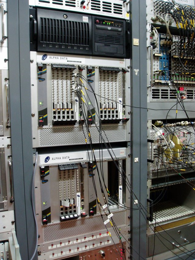 The TMS was designed in a modular way. At the top level there is a Linux based host system that is responsible for control, data gathering and communications with external system. Beneath this there are 3 single CompactPCI board computer modules, again running Linux. One of these is situated in each 8-slot rack unit. These are responsible for controlling and passing data from the 5 PUPE boards that do the front-end data acquisition and real-time data processing work. We used Concurrent Technologies PP 410/03x for this role. These module controllers also use the Linux OS.
We have used this basic structure in a number of projects. It uses the flexibility of PC hardware running Linux at the higher levels and the raw processing power of FPGA's at the lower level front end to do the real-time acquisition and initial data processing work.
The software is written in 'C++' and uses a special, BEAM developed, RPC mechanism called BOAP to perform the inter-board communications. This uses QOS protocols to provide real time performance over the switched Gigabit Ethernet internal network.
The FPGA Processing Board
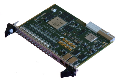 The FPGA processing, PUPE, board was specially designed for the system although its capabilities would be useful in many other applications. The boards, designated ACP-FX-N2/125, utilise a Xilinx Vertex-4 FX100 FPGA, 1GByte of DDR2 SDRAM and have nine 125MHz 14bit ADC's. The boards core design is based on Alpha Data's ADM-XRC/FX100-10/1G FPGA PMC module providing a high degree of FPGA firmware compatibility with this hardware. The design employs a low jitter, PLL synchronised, clock source for the ADC's. The master clock for these can be external to the board allowing multiple boards to be synchronised at the ADC clock level.
As well as the 9 ADC inputs there is one 10MHz clock input and 13 digital I/O signal lines for timing and other system control functions. There are an additional 8 digital lines reserved for inter-board synchronisation.
The board employs a second Xilinx Virtex-4 LX25 device for Compact PCI interface duties. This uses the PCI bus FPGA firmware as developed by Alpha Data for their existing PMC boards. The PUPE also has two Gigabit Ethernet PHY's with the associated RJ45 connectors on the front panel connected directly to the FPGA. Thus either CompactPCI or Gigabit Ethernet can be used for system communications.
The FPGA firmware is written in VHDL.