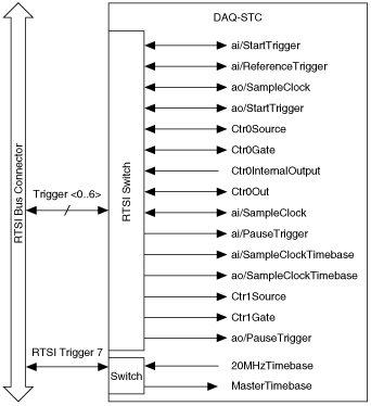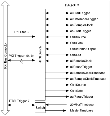
The seven RTSI trigger lines on the RTSI bus provide a very flexible interconnection scheme for any device sharing the RTSI bus. These bidirectional lines can drive or receive any of the timing and triggering signals shown below directly to or from the trigger bus. The RTSI trigger lines connect to other devices through the PXI bus on the PXI backplane or through a special ribbon cable that must be installed for PCI. The following figures show the PCI signal connection scheme and the PXI connection scheme.
In PCI, you can access RTSI <0..6> through the RTSI cable. With PXI S Series devices, RTSI <0..5> connects to PXI Trigger <0..5>, respectively, through the S Series device backplane. RTSI 6 connects to the PXI star trigger line, allowing the device to receive triggers from any star trigger controller plugged into Slot 2 of the chassis. For more information about the star trigger, refer to the PXI Hardware Specification Revision 2.1.


Refer to Timing Signal Routing for a description of the signals shown in the figures.