AI Sample Clock Signal
You can use the AI Sample Clock (ai/SampleClock) signal to initiate a measurement. Your S Series device samples the AI signals on all channels once for every occurrence of ai/SampleClock. A measurement acquisition consists of one or more samples.
The source of the ai/SampleClock signal can be internal or external. You specify whether the measurement sample begins on the rising edge or falling edge of the ai/SampleClock signal.
Using an Internal Source
By default, ai/SampleClock is created internally by dividing down the ai/SampleClockTimebase.
Several other internal signals can be routed to the sample clock. Refer to Device Routing in MAX in the NI-DAQmx Help for more information.
Using an External Source
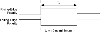
You can use a signal connected to any PFI or RTSI <0..6> pin as the source of ai/SampleClock. The following figure shows the timing requirements of the ai/SampleClock source.

Outputting the AI Sample Clock Signal
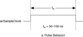
You can configure the PFI 7/AI SAMP CLK pin to output the ai/SampleClock signal. The output pin reflects the ai/SampleClock signal regardless of what signal you specify as its source. Your DAQ device briefly pulses the PFI 7/AI SAMP CLK pin once for every occurrence of ai/SampleClock.
The following figure shows the timing of pulse behavior of the PFI 7/AI SAMP CLK pin when the pin is an output.

The PFI 7/AI SAMP CLK pin is configured as an input by default.
Other Timing Requirements
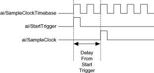
A counter on your device internally generates ai/SampleClock unless you select some external source. The ai/StartTrigger signal starts this counter. It is stopped automatically by hardware after a finite acquisition completes or manually through software. When using an internally generated ai/SampleClock in NI-DAQmx, you can also specify a configurable delay from the ai/StartTrigger to the first ai/SampleClock pulse. By default, this delay is two ticks of the ai/SampleClockTimebase signal.
The following figure shows the relationship of the ai/SampleClock signal to the ai/StartTrigger signal.


