Triggering with an Analog Source
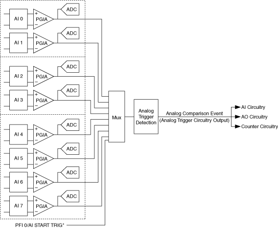
Some S Series devices can generate a trigger on an analog signal. The following figures show the analog trigger circuitry.

You must specify a source and an analog trigger type. The source can be any analog input channel. On the NI 6110/6111 and NI 6115/6120, the source can also be the PFI 0/AI START TRIG pin.
PFI 0/AI START TRIG Pin
This pin is an analog input when configured as an analog trigger. Therefore, it is susceptible to crosstalk from adjacent pins, resulting in false triggering when the pin is unconnected. To avoid false triggering, ensure that this pin is connected to a low-impedance signal source (less than 1 kΩ source impedance) if you plan to enable this input using the application software.
Analog Input Channel
You can select any analog input channel to drive the instrumentation amplifier. The instrumentation amplifier amplifies the signal as determined by the input mode and the input polarity and range. The output of the instrumentation amplifier then drives the analog trigger detection circuit. By using the instrumentation amplifier, you can trigger on very small voltage changes in the input signal. For more information, refer to Analog Trigger Accuracy.
Analog Trigger Actions
The output of the Analog Trigger Detection circuit is the Analog Comparison Event signal. You can program your DAQ device to perform an action in response to the Analog Comparison Event signal. The action can affect the following:
 | Note Refer to Timing and Triggering in the NI-DAQmx Help for more information. |

